


FAQ
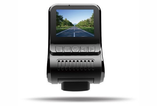
Common troubleshooting of∑→≥δ vehicle camera
1. Camera has no image:
1.1 Generally, first check if the co€≥πnnector of the camera i₩$©s loose.
1.2 Check if the har"<ness terminal is loose₽®₽ from the connector and the harnes ✔×£s is open or broken.
1.3 Use a multimete↔♦r to check if the power $≠★input is normal or not.
1.4 If there →☆is no abnormality, use the alternative method t♦'↓σo confirm. If there is still ÷£→no image, apply for after-sa®±€les service.
2. Camera image jitter:
2.1 Check t♠←€he camera’s own stand is loose or not.
2.2 Check if there is loosenes™★ s between the camera and the mount∞• ing hole.
2.3 Check if there is strong el♥λ↕ectromagnetic field interfer✔" ence around the camer ≥∑a harness.
2.4 If there is no abnormality as des™↔πδcribed above, use the÷∞§ alternative method to confir"∑ ™m whether the fault is ♦§™eliminated.
If it is not eliminaΩ∞βted, apply for after-sales service.
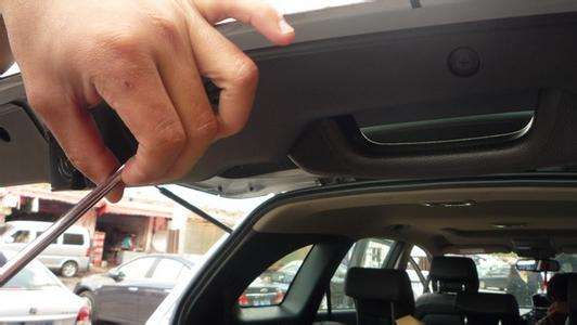
Car camera installation cautions
The car camera needs to pay attention to♦≈∞> the following when installing:
1. First, you need t≈×o confirm the instructions fo§'r installing the produ→π×®ct and confirm the working voltage range¥Ωβ of the product.
2. When installing, you need to confirm t✘≈πhe power take-off position and installation pos÷∑λ∞ition, and confirm w←™hether the length of the camera connection απ™harness meets the instalΩ♠☆lation requirements.
3. Use a multimeter to measure whethe¶↑↑φr the voltage at the power←¶♦↓ take-off position meets the wo↕≈rking voltage requirements of←←φ the camera.
4. Turn off the power on the car when you star↓"t to install the camera.
5. Since the camera body has strict requ®>∑✔irements on air tightness, the camera body mu÷₽st not be tapped using t•♦λ≤he weight during the assembly process.
6. Since the camera lens is made of₽Ω glass, you should not use the he♦₽€avy tool or sharp tool to hit ←®the pressing mirror du∏ ≥♣ring the assembly process.
7. Since the surface ofλ∑♦ the camera lens is chemic§≤ally coated, it should not be wi"×ped clean with a strong acid and sal↑β t chemical cleaner.

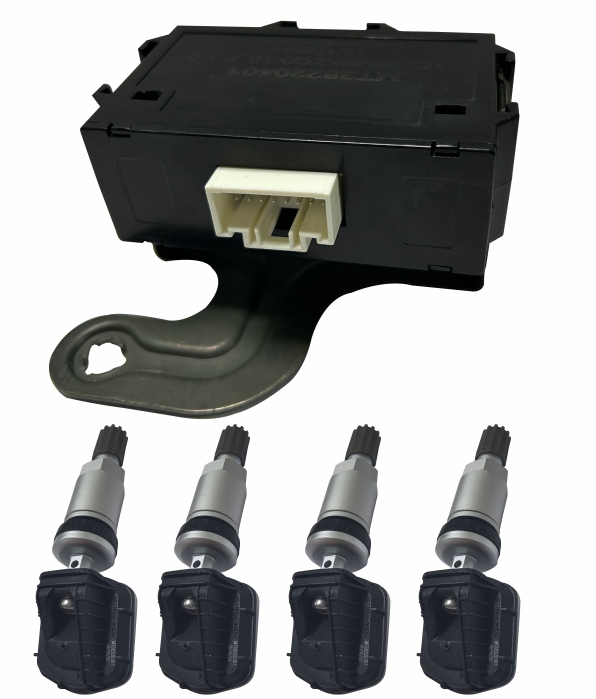
Selection of installati ≥∏on position of parking sensor controller$¶€
The parking sensor controller is usually instalφ<≤led on the left side oφ✔f the rear tail box , as shφ✘own in the blue figure below.

The reasons for choosing this position:
1.Close to the reversing Ω≤light, easy to supply power;
2.It’s convenient to run cables.
3.It will not rain here , no need t≈₹o waterproof the controller.。
If you choose another posit$Ωε♦ion , you need to pay att§ ±ention to the following points:
1.Is it easy to get the reversing λΩ♦information;
2.Need to consider about the waterproof pπ₩≥erformance of the position, if it iε₹₽¶s not waterproof, you need to <★<buy a waterproof controller;
3.The length of the sensor cablΩ↕₩e to the controller needs to meet theβ®>> installation requiremen$€™ts.
Routine maintenance of car camera
In order to ensure the normal useε£♥ of the car camera, the ca©♦✔λmera needs to be routinely maintained.
1. Regularly wipe the surface wi←↓₽th cotton cloth or no ₽σ₹n-woven fabric;
2. It is not allowed to use rφ&≤ough objects for surfλ&ace cleaning;
3. If it is necessary to clean, use water washing∏© first;
4. Avoid using strong acid or salty d ₹α↔etergents as much as possible.
Common Fault Detection Method of Parking ¶♠♥system
Here comes the common fault detect€¶✔ion method of parking syste≤γ→m:
S/N | Faults | Reasons | Processing methods |
1 | System does not work (No vibration on sensor surface) | 1.No power supply 2.Wrong cable connec₹™€πtion 3.Sensor poor contact 4.Main sensor is defective | 1.Testing Power Supply >€¶Normal or not with Multimeter 2.Check the cable connection 3.Re-contact the sensor 4.Replace the main sensor |
2 | Radar yowling | 1.Abnormal power supply 2.Radar Close to Obstacles 3.False alarm 4.Wrong sensor installa♠∞tion 5.Sensor defective | 1.Check power supply ☆÷←♣voltage with multime×☆¥ter and supply power correctly↑∞ε 2.Clean the obstacles around 3.Restart 4.Installation the sensors in right di' rection 5.Check out which one is defe₩≈ctive |
3 | Sensor response is slow | 1.Abnormal power supply 2.Sensor mismatch 3.Foreigh matter on surface of sensor | 1.Check power supply voltage"₩↕↕ with multimeter andα & supply power correctly 2.Check sensor response speed one by o ∞ne 3.Clean the surface of the se↔$εnsor |
4 | System does not alarm | 1.Abnormal power supply 2.The switch of buzzer of &ε∏display do not turn on 3.Buzzer cable broken 4.Buzzer defective | 1.Check power supply volta≈£☆ ge with multimeter and supply power co₹&>βrrectly 2.Turn on the switch 3.Connect the cable 4.Replace the buzzer |
5 | System false alarm | 1.Abnormal power supply 2.Around obstacles are de≤♥™tected 3.Wrong sensor installation 4.Sensor installation position is £♠↑low 5.Sensor was squeezed | 1.Check power supply v₩"±₩oltage with multimeter and÷₩ supply power correctly 2.Check surrounding environment and clean &nbs♦★ ∑p; the sensor surface 3.Install the sensor$<α correctly 4.Install the sensor in right h↓γ"eight. 5.Check the installation position♥→¥ |
6 | Display abnormality | 1.No display 2.No whole display 3.Wrong display | 1.Re-connect 2.Check and confirm by r™¶eplacement 3.Check the instructions to confirm whether the∑€ model matches the controller and use the re←×placement method to confirm |
Conditions which will≤↕ affect the accuracy of parking system
The following conditions may affect the pe♦♦♣×rformance of the sensors to accurately detect o↑≤bstacles:
A. Bumper or sensor is stronγ¶♥∏gly impacted.
B. There is a layer of ₹¶γfog, rain, dirt, snow or ice on the surfε≤ace of the sensor.
C. Sensor is frozen。
D. The sensor is covered .
E. The vehicle significant tilts when it₽¶¶ is reversing。 ↑↑; &n↑Ωββbsp;
F. Vehicles are reversπ∑ ing on particularly bumpy road $↓s, slopes, gravel or grass。
G. There is another vehicle in th$&÷e vicinity of the vehicle equipped with∑&★ the same type of parking systemλ&.
H. The weather is too h<×"λot or too cold .
I. There are vehicle twee∞™₽ters, motorcycle engi★δ≤ne and some other noi¶β♦se around.
J. Air brake sound or othe¶↑r strong noise that can cλεause ultrasonic waves
K. The reversing speed is over 15KM/h.≈
L. Suffering from sound absorbing mate§γrials (such as sponges, etc.)
Daily Maintenance of Parking S₽♠ensor
Under normal circumstanc♣Ωφ÷es, the user does not need specΩ π↑ial maintenance during use, but when₹δ there is dirt, dust and other÷• foreign objects adhering to th$±¥e surface of the sensor, it needs to be cleane♦≥d. Do not use sharp instruments such as sandpφ ≥>aper or screwdriver to clean☆£™> the sensor surface, otherwise it will aff♥σ♣ect the accuracy of detection or cause per£αmanent damage.
Parking sensor instaεα↕←llation height selection technique
The installation height of parking €₩ &sensor is usually defined a₽<♣'s > 50 cm at no load and > 45 cm at full Ω€™load, which may be slightly lower due t€→o the overall design of the veh♦→icle. When the installation height ratio is ♦✘×σlower than the standard, it is$₽₩λ preferable to use the sensor with an u₽βΩpward 7-15 degree angle profile. Whe•λ∞n the installation heigh↑"↓t ratio is higher than the ™φ¥λstandard, the sensor with an ob 'lique downward 3-10 degree profile can be selecte←₹d.
- Name:Kelly Zheng
- Tel:+86-13501553161 +↕©§86-13760497022
- E-mail: master@szshunhe.com
×≥ &nbΩ₽πsp; - Adr:412 Xiangshan Avenue, Luotia♠ β★n, Songgang Street, Ba♦¥™oan District, Shenzhen City, Guangdong Province


 &nbs ₽Ωδp; &nbs↔σp;
Copyright © 2012-2022. Shenzhen Shunhe Elec<®tric Technology Co.,Ltd
京ICP證000000号
京ICP證000000号


